Wenn Sie die Graphik nicht erkennen können, verwenden Sie einen Browser mit Zoom. Oder downloaden und öffnen mit open office. Es werden alle Details übertragen.
Wenn
Sie die Graphik nicht erkennen können, verwenden Sie einen
Browser mit Zoom. Oder downloaden und öffnen mit open office. Es
werden alle Details übertragen.
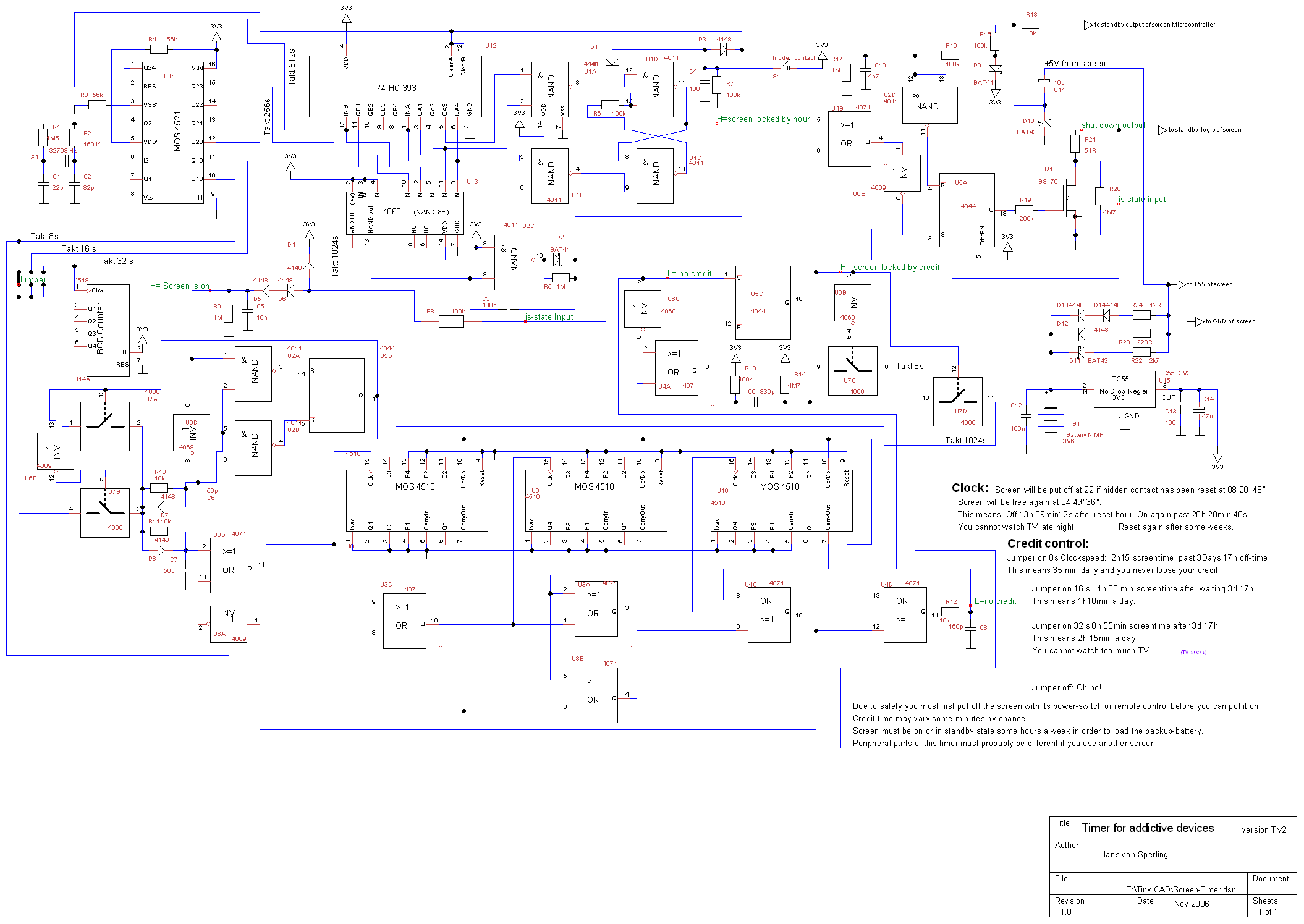
Description of the schematic:
The screen-timer is a small CMOS- device, which was designed to be hidden inside a computer-screen or a TV. It consists mainly of two parts: The daytime-timer and the credit-timer which work together on one output.
Daytime-timer: The clock is provided by the crystal oszillator with X1 and U11. It is divided by U12 and reset daily by U13. U2C inverts the clock signal because this lot of the 4068 didn't have the AND-output.
C3, D2 and R5 extend the reset pulse for proper reset.
The clock must be set by the hidden contact S1 (e.g. a reed-contact) at a special time. You can vary the off hour by changing the set-hour. It should be enough to set the clock every two month. If the of-hour is reached, U1A provides a low output and sets the Flip-Flop U1D-U1C. Hours later it is reset by U1B.
If this F-F is set, U5a is set over U4B U8E. It is U4B which combines the clock and the credit to one free/locked - signal.
But if the screen would be put off by this, it could happen, that it is put off by the timer and you think: My TV is off. But when you are away and don't know it, your TV will be put on again. To avoid this, U5A must first be reset by the Microcontroller of the TV (Remote control) or by switching the TV's power off, before it can be put on again. This service is provided by the U5A.
The whole device consumes continually about 300uA. This means, the backup battery should be good for at least one week. But if you always use the power switch of the TV instead of the remote control, like you should, the battery must be loaded within 2h15min.That's some stress for the battery. A reduction of the load current for the fully loaded battery is provided by D11-14 and R22-24. This works only, of course, if your TV has a standby power of about 4,8-5,2 V. Should be 5.0 .
All Schottky Diodes in the timer are used because of their low forward voltage, not their speed. Don't replace them by usual Diodes! The exact values of most capacitors and resistors are not very critical. 10%-items should be good enough for all.
The credit timer consists of an up/down counter from zero to 999. The is-state input must be connected to any power line of the TV which has only power, if you watch TV. The tension should not exceed 20V because the battery is loaded to much by the clamping with D4. But of course you can choose a bigger R8. In this TV the is-state could use the same wire as the output. So they are connected here. The Transistor Q1 will shut down the TV-power to standby. Of course you can shut down the color or sound as well, or what you like.
The credit-timer works with two different clocks: One provides a pulse every 320 seconds. This comes from the output Q3 of the U14A. The other, faster, clock provides a pulse every 8, 16 or 32 seconds, dependent on what you choose with the jumper. Dependent on the tension on the is-state input either U7B or U7A is conductive and you get the slow or the choosen fast clock signal for the counter. The counter is also dependent from the is-state input: It counts up or down. So it counts slowly up your credit if your TV is off, but it counts down much faster if you watch TV. If it reaches 000, the TV is put off. The ratio is set with the jumper. 8s means a ratio of 40 or half an hour TV a day, 32 means ratio 10 or two hours a day. But the 4510 makes some ugly problems: It needs additional or - gates for working properly in cascade: U3C , U3A.
And it must not receive a change at the up/down input, while the clock input PIN 15 is low. This is provided by the transparent D-type FF U2A, U2B, U6D, U5D. If you used a 4013 instead of all those, the timer would react to slowly on changes on the is-state input. The R10/11 C6/7 D7/8 make sure, that the edges of the signal don't come to early or to late.
If the counter has reached the zero or 999 the clock is inhibited by the carry signal from U4C, U6A, U3D, dependent on the counting direction. Of course it must not count down from 000 to 999!
If the counter provides carry, while you count down this is detected by U4D. This means, your credit is expired. R12, C8 remove all spikes which might be produced by the delay of the carry-logic.
If this credit signal is low, U5C is set, and we arrive at U4B, which we already know from the daytime timer above.
If your TV is put off by credit, you have to wait about 10 min at least, before you got the chance to switch it on again. So you can't watch TV by always switching on and off. This is made sure by U5C, U6C, U4A, U6B, U7C,
U7D. Due to the clock selector the FF U5C will notice very fast, that your credit is expired, but the output needs long time to notice, if you have put your TV off.
Thanks to C11, D10, R18 which have been installed later, the safety FF U5A is not only reset by the Microcontroller (remote control) but also, if the power-switch of the TV is off. These parts and the U2D have not been needed for the TV, I had made up before.
p.s.:TV sucks